Difference between revisions of "Introduction to Graphics Shapes"
m (Text replacement - "</source>" to "</syntaxhighlight>") |
|||
| Line 212: | Line 212: | ||
'''PREV.''': [[Introduction to Graphics]]<br/> | '''PREV.''': [[Introduction to Graphics]]<br/> | ||
'''NEXT''': [[Introduction to Fonts]] | '''NEXT''': [[Introduction to Fonts]] | ||
| + | |||
| + | |||
| + | {{GIDEROS IMPORTANT LINKS}} | ||
Latest revision as of 22:19, 18 November 2023
The Ultimate Guide to Gideros Studio
Graphics: Shapes
Shapes
Gideros provides a Shape class for drawing primitive shapes. It is similar to the drawing API found in Flash although at the moment it only has a subset of Flash’s capabilities. Since the Shape class inherits from Sprite (which itself inherits from EventListener), instances of the shape class can be rotated, scaled, positioned on the screen, listen for and dispatch events - basically anything that Sprites can do. See the chapter on Sprites for a full list of inherited capabilities.
The unique functions added by the Shape class are:
| Function Name | Description |
|---|---|
| Shape.new() | Creates a new Shape object |
| Shape:setFillStyle(type, …) | Sets the fill style for a shape |
| Shape:setLineStyle(width, color, alpha) | Sets the line style for a shape |
| Shape:beginPath(winding) | Begins a path |
| Shape:endPath() | Ends a path |
| Shape:moveTo(x,y) | Moves the pen to a new location |
| Shape:lineTo(x,y) | Draws a line from the current location to the specified point |
| Shape:closePath() | Draws a line from the current location to the first point in the path |
| Shape:clear() | Clears all paths from the shape and resets the line and fill style to default values |
One question that you might ask is: Why draw using this primitive API? Wouldn’t it be better to use some other authoring environment (e.g., Photoshop, Inkscape, Gimp) then import the image as a Texture? In most cases, an authoring tool is the right answer. However, there are cases where you don’t know which graphics you need in advance:
   • Drawing tool (e.g., drawing lines based on user input)
   • Graphs (e.g., stock prices, bar-charts)
   • Graphics equalizer in a music player
   • Skinning physics engine soft bodies
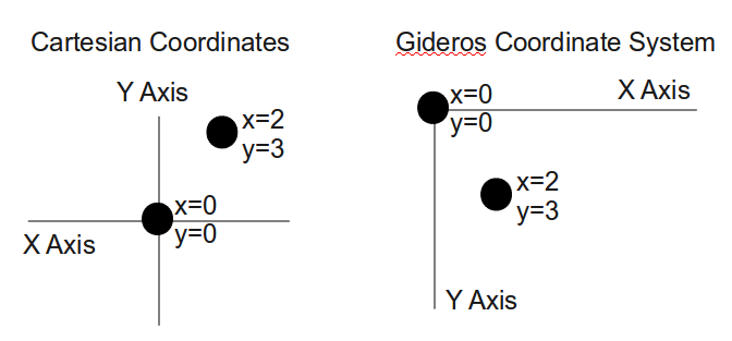
Gideros coordinate system
The standard cartesian coordinate system that everyone learns in school consists of an origin point (x=0, y=0) which is often drawn in the center of a page. The x values increase to the right horizontally and the y values increase upwards vertically (i.e., x values are negative to the left of the origin and positive to the right, y values are negative below the origin and positive above).
The origin point in the Gideros coordinate system is in the upper left-hand corner of the screen with an inverted y-axis (i.e., y values are negative above the origin and positive below the origin). The x-axis is the same as the standard cartesian coordinate system.
Usage overview
Shapes consist of zero or more paths. Each path consists of zero or more lines with the same line and fill style. A different line or fill style can be used for each path. Since a path can only have one line style and one fill style, multiple paths are required to use different line / fill styles within a shape.
A pen & paper analogy is often used to describe the drawing approach used by the Shape class. The “moveTo” function can be thought of as lifting a pen off the paper and moving it to a different location without drawing anything. The “lineTo” function draws a straight line from the current pen location to the destination location.
The overall flow for drawing with the Shape class is:
   • Create a new shape
   • For each path that you want to draw;
   • Begin the path
   • Set the fill style (fill or line must be set for the shape to be visible)
   • Set the line style (fill or line must be set for the shape to be visible)
   • Move pen and draw lines
   • Close the path (optional)
   • End the path
Drawing your first line
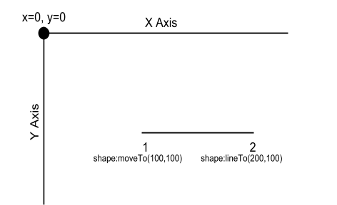
Our first drawing will be a simple horizontal line from x=100,y=100 to x=200,y=100 as shown in the following figure. We’ll use the moveTo function to move to the first point, then the lineTo function to actually draw the line.
Here’s the code to draw the line:
local shape = Shape.new() -- create the shape
shape:beginPath()         -- begin a path
shape:setLineStyle(1)     -- set the line width = 1
shape:moveTo(100,100)     -- move pen to start of line
shape:lineTo(200,100)     -- draw line
shape:endPath()           -- end the path
stage:addChild(shape)     -- add the shape to the stage
Some things to note about this code:
- without the call to setLineStyle, the line wouldn’t have been visible -- in this example, we used setLineStyle to set the line width to 1 (the default line color is black)
- we added the shape directly to the stage. For this example that’s good enough. For more complicated examples you’d probably use some other parent. Most of the following Shape examples will use this same approach.
Drawing a Rectangle
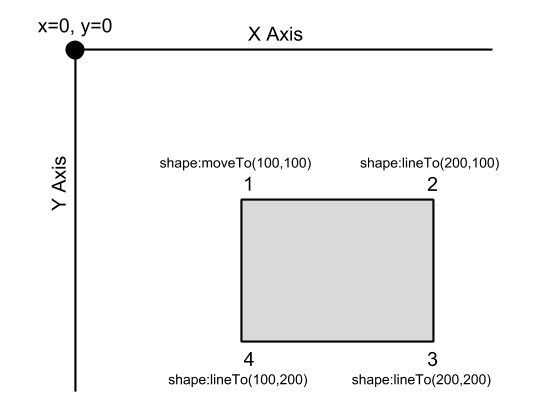
Lines aren’t very interesting so let's expand our line into a filled rectangle. We’ll draw the rectangle with the upper left corner at 100,100 and the lower right corner at 200,200. We’ll also fill the rectangle with a boring gray color.
local shape = Shape.new() -- create the shape
shape:beginPath()         -- begin a path
shape:setLineStyle(1)     -- set the line width = 1
shape:setFillStyle(Shape.SOLID, 0xcccccc) -- NEW: boring gray
shape:moveTo(100,100)     -- move pen to start of line
shape:lineTo(200,100)     -- draw top of rectangle
shape:lineTo(200,200)     -- NEW: draw right side of rectangle
shape:lineTo(100,200)     -- NEW: draw bottom of rectangle
shape:lineTo(100,100)     -- NEW: draw left side of triangle
shape:endPath()           -- end the path
stage:addChild(shape)     -- add the shape to the stage
This example is similar to our line drawing program plus 1 additional line to fill the rectangle and 3 additional new lines to draw the right, bottom, and left sides of the rectangle.
Drawing Arbitrary Polygons
There are a couple of simplifications that we can make to the rectangle code:
- The call to moveTo can be replaced with lineTo. The first call to lineTo after a path is started behaves just like a moveTo.
- Although a rectangle has 4 points, we have to use a total of 5 moveTo/lineTo calls -- the first point has to be used twice (once for the initial moveTo command and once to close the rectangle with the final lineTo call). The last lineTo command can be replaced with a call to closePath. The closePath function is equivalent to a lineTo command to the first point in a path.
The following code uses these two simplifications to draw a polygon from an arbitrary list of data points:
local path = { {100,100}, {200,100}, {200,200}, {100,200} }
local shape = Shape.new()
shape:setLineStyle(1)
shape:setFillStyle(Shape.SOLID, 0xcccccc)
shape:beginPath()
for i,p in ipairs(path) do
	shape:lineTo(p[1], p[2])  -- lineTo used for all points
end
shape:closePath()  -- connect last point to first point
shape:endPath()
We can change path to have as many points as we’d like and the above code will draw the closed polygon.
path = { {x1,y1}, {x2,y2}, … add as many points as you want … }
Shape Anchor Point
Shapes are “anchored” at the graph origin (0,0). The anchor point affects how the shape behaves when manipulated (e.g., rotated, scaled). If we were to rotate the rectangle we drew earlier by 90°, the rectangle would have rotated off the screen since it would have rotated about the (0,0) origin point. The anchor point also affects scaling -- scaling the rectangle would have moved it further away from (0,0) if it was enlarged and closer to (0,0) if we’d scaled it down.
Let’s change our previous polygon example so that the rectangle will stay centered at its center point (150,150) if rotated or scaled. The code will need the following two changes:
   • Draw the rectangle centered at (0,0)
   • Use the inherited Sprite:setPosition function to position the shape
We can make these changes by modifying the first few lines of our previous example like so:
local path = { {-50,-50}, {50,-50}, {50,50}, {-50,50} }
-- CHANGED: points are now centered around (0,0)
local shape = Shape.new()
shape:setPosition(150,150) -- NEW
-- ... the rest of the original example would go here …
Line and Fill Styles
We’ve used setLineStyle and setFillStyle in our examples, but the lines and rectangles that we’ve drawn so far are pretty boring. This section provides more details on these two functions.
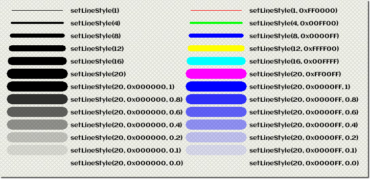
The setLineStyle function has one required parameter (width) and two optional parameters (color, alpha): width: width of the line (integer number > 0) color: color value of the line (optional hexadecimal number, default = 0x000000) (red is 0xFF0000, blue=0x0000FF, green=0x00FF00, white=0xFFFFFF, etc.) alpha: alpha value for the line (optional floating point value between 0 & 1, default=1) (0 = invisible, 0.5 = 50% transparency, 1 = no transparency)
The following figure shows some example line styles.
Shapes can be unfilled, filled with a color, or filled with a texture. The first argument to setFillStyle determines the fill type:
- Shape.NONE: Clears the fill style (i.e., the shape will not be filled)
- Shape.SOLID: Sets the fill style as a solid color. In this mode, an additional color parameter is required (hexadecimal number). An optional alpha value (floating point number between 0 and 1) can also be specified.
- Shape.TEXTURE: Fills the shape with a tiled texture. In this mode, and additional texture argument is required. An optional transformation matrix can also be specified.
The following illustrates how to use the three different types of fill styles:
setFillStyle(Shape.NONE) -- unfilled
setFillStyle(Shape.SOLID, 0xff0000) -- fill solid red color
setFillStyle(Shape.SOLID, 0xff0000, 0.5) -- fill with red, 50% transparency
local texture = Texture.new("image.png")
setFillStyle(Shape.TEXTURE, texture) -- fill with texture
local matrix = Matrix.new(0.5, 0, 0, 0.5, 0, 0)
setFillStyle(Shape.TEXTURE,texture,matrix) -- fill with texture scale x/y by 0.5
There are two important things to note when using texture fills:
- If the shape of the texture is smaller than the area to be filled, Gideros will tile the textures in both the x and y dimensions. The tiles will be aligned so that the upper left-hand corner of the texture will be at x=0, y=0 (unless this is modified by a transformation matrix).
- If the width and/or height of the texture is not a power of 2, Gideros will increase the width/height to be a power of 2 with the expanded area left unfilled or transparent. For example, a 33 (width) x 123 (height) texture will be re-sized to 64 x 128 then tiled as necessary.
As stated previously, all lines and drawn shapes within a path share the same line and fill style. Gideros applies the most recently specified line and fill style when each path is ended (i.e., with endPath). The following code draws a shape with 2 paths. Everything drawn between a beginPath/endPath pair will have the same line and fill style. In other words, even though setLineStyle is called 5 different times, only 2 of them have an effect because there are only 2 paths.
local s = Shape.new()
s:setLineStyle(1)
s:beginPath()
s:moveTo(10,10); s:lineTo(20,10) -- line width will be 1
s:endPath()
-- All lines in the following path will have a width of 3.
-- Only the setLineStyle call right before endPath has an effect
s:beginPath()
s:setLineStyle(1)
s:moveTo(10,10); s:lineTo(20,10) -- line width will be 3
s:setLineStyle(2)
s:moveTo(10,10); s:lineTo(20,10) -- line width will be 3
s:setLineStyle(3)
s:endPath()
s:setLineStyle(4)
Winding Rules
Simple paths such as circles, triangles, rectangles have a well-defined and obvious “fill area.”. For complex paths (e.g., concentric circles, shapes with intersecting lines), multiple choices can be made as to whether fill an area. The Shape:beginPath function takes an optional winding argument that determines how the path will be filled (the default value for the argument is Shape.EVEN_ODD). To determine whether an area should be filled, the following two rules are available within Gideros:
- Even-odd rule (Shape.EVEN_ODD)
- Draw a line with a start point in the area to be filled extending to infinity in any direction
- If the line crosses an even number of lines, the area should NOT be filled
- If the line crosses an odd number of lines, the area should be filled
- Non-zero rule (Shape.NON_ZERO) - this rule depends on the drawing direction (or winding) of the edges of the path. When paths of opposite drawing direction intersect, the area will be unfilled.
- Draw a line with a start point in the area to be filled extending to infinity in any direction
- Start with a count of 0
- Every time the line crosses a line of the polygon drawn in one direction add one to the count. Subtract one from the count for every edge drawn in the opposite dimension.
- If the ending count is zero, the area should NOT be filled. If the ending count is zero, the area should be filled.
For example, consider a simple path such as a rectangle: a line started from “outside” the rectangle will either cross 0 edges or 2 edges. Since the line crosses an even number of lines, the area should not be filled using the even-odd rule. The area wouldn’t be filled with the non-zero rule either: the line would either cross 0 edges (count would be 0) or two edges -- one edge drawn in one direction, the other edge drawn in the opposite direction (the count would be 0). If a line is started inside the rectangle, the line will intersect one edge (an odd count for the even-odd rule, and a count of either -1 or 1 for the non zero rule).
In can be confusing to decide whether an area should be filled but thankfully examples of different winding rules are easy to find since these two winding rules are used in flash, SVG, postscript, and many other drawing technologies.
PREV.: Introduction to Graphics
NEXT: Introduction to Fonts


